Note: This class loosely follows up on Photorealistic Graphics (NPGR004) and is aimed mostly at students with a deeper interest in realistic rendering methods.
Course information 2023/2024
| Lectures: | Fridays, 9:00 – 10:30, room S9 | Contact: Tomáš Iser |
| Practicals: | Fridays, 10:40 – 12:10, room S9 | Contact: Tomáš Iser |
As you can see, the lectures and practicals are scheduled right after each other. In reality, there is a certain overlap and I will try to introduce math problems and exercises from the practicals already during the lectures.
Lecture and practicals content and assignments for 2023/2024 will be updated throughout the semester.
Lecture content
I am preparing modified slides for this semester 2023/2024, so I will be adding them here as they are presented. For older materials, please refer to the archived lecture information at the bottom of this page.
Date |
Lecture topic |
Slides |
| 6 October | Introduction + Homework Assignment 0 | |
| 13 October | Elementary math & physics in rendering Light transport theory, radiometric quantities, Lambert’s cosine law, inverse-square law, IES light profiles, spectral response and colors, spherical coordinates, solid angle and differential solid angle, integrals and various exercises on integrating on a unit sphere |
|
| 20 October | BRDF (How does light reflect on various materials?) Interaction of light with a surface, bi-directional reflectance distribution function (BRDF), BRDF properties, reflection equation, reflectance, albedo, examples of BRDF (ideal diffuse, ideal mirror, ideal refraction, Snell’s window, radiance compression, Fresnel equations, retroreflection, microfacet models – all including formulas and explanations) |
|
| 27 October | Monte Carlo for rendering & direct illumination + Homework Assignment 1 (C++) | |
| 3 November | Monte Carlo for rendering & direct illumination (continued) | |
| 10 November | Importance sampling, rendering equation and its solution + Homework Assignment 2 (C++) | |
| canceled (bank holidays) | ||
| 24 November | Multiple importance sampling (MIS) + Homework Assignment 3 (C++) | |
| 1 December | Volumetric light transport & participating media | PDF, advanced course |
| canceled (graduation ceremony) | ||
| 15 December | Bi-directional path tracing (BDPT), photon mapping (PM), irradiance caching (IC) + Homework Assignment 4 (C++) | BDPT, PM, IC |
| canceled (all teaching canceled at Charles University) | ||
| 5 January | BDPT, PM, IC (continued) | |
| 12 January | Inverse & differentiable rendering |
Assignment 0 (Creative exercise in a 3D editor) [total: 10 points]
Please see the slides from the first lecture.
Assignments 1-4 (Writing a C++ path tracer) [total: 35 points]
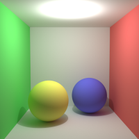
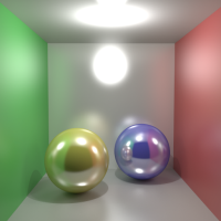
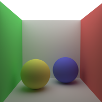
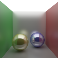
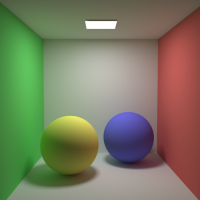
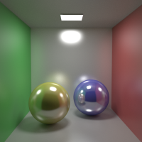
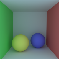
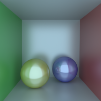
The goal of these assignments is to write a Monte Carlo path tracer. We provide you with a small skeleton of our custom C++ framework, which can handle basic tasks such as saving an image, writing colors to pixels, generating camera rays, detecting scene intersections, a simple parallel execution, etc. It also provides abstract classes and methods that you should fill with your own code. The basic piece of C++ code that we provide can already handle rendering direct illumination from a point light source in a scene with only diffuse surfaces. Your goal in each assignment is to expand the C++ solution with new functionality. In the end, as you complete all the assignments, you will reach a fully working Monte Carlo path tracer that computes global illumination and produces the following images on the 8 sample scenes that are part of the source code:
 |
 |
 |
 |
| Isotropic point light Diffuse surfaces |
Isotropic point light Glossy surface |
Large area light Diffuse surfaces |
Large area light Glossy surface |
 |
 |
 |
 |
| Small area light Diffuse surfaces |
Small area light Glossy surface |
Const. environment map Diffuse surfaces |
Const. environment map Glossy surface |
Working with the C++ solution
First, download our initial C++ project. It contains a CMake file and a directory with C++ source code. The easiest way to compile the solution into an executable is to download and run CMake on the provided project, which should work on all standard platforms like Windows, Linux, and Mac using a C++ compiler that supports C++17 and OpenMP. Please note that I cannot assist you with compiling C++ projects on your specific computer, but the general approach using CMake is to run the following commands from the place with the C++ project:
mkdir build
cd build
cmake ..
to create a build directory, and initialize CMake there, and then:
cmake –build .
to compile (build) the solution into an executable.
Submitting your C++ solutions
Submitting your C++ solutions is done via ReCodEx. You can join the NPGR010 group either by linking your account via SIS, or by following an invitation link that I sent you in an e-mail. When submitting your solution, simply upload all the .cpp and .hpp source files. Do not upload the CMake file. ReCodEx will then attempt to compile the solution. Once it succeeds, it executes your solution on the 8 demo scenes, and it compares the output images to the reference images. If the mean difference is within a given threshold, you get an OK. You can also see which exact scenes did not pass.
Please note that ReCodEx only compares the output images, but does not check if your source code really follows the instructions! For example, all assignments 1 to 3 result in the same images, meaning you could technically upload the same solution 3 times and still pass the ReCodEx checks successfully! This means that I need to check each of your solution’s source codes manually to verify that you really followed the instructions. The ReCodEx verification is just intended to help you make sure your images are correct!
Assignment 1: Direct illumination calculation through explicit light source sampling [5 points]
The first three assignments will be about direct illumination, meaning only 1 bounce between camera and light (camera → surface → light). The initial version of our C++ code can only correctly render the first scene, the other ones are either incorrect or fail to run because of missing functions. In your first assignment, you should expand the initial C++ code to support direct illumination in all 8 demo scenes. This means the following:
- You need to change the material implementation in materials.hpp to correctly handle the glossiness in the BRDF evaluation.
- You need to change the lights implementation in lights.hpp to correctly handle sampling points on area and environment (background) lights.
- For the light sources, you can (but do not need to) add your custom utility functions in utils.hpp. Specifically, it is useful to implement functions that sample a random point on a uniform triangle (for the area lights, which consist of 2 triangles) and on a uniform sphere (for the environment light; the derivation can be found here in the same section as hemisphere).
- You will need to edit pathtracer.hpp to correctly handle the situation where the ray directly hits the area light, in which case you want to evaluate its radiance directly.
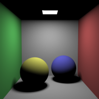
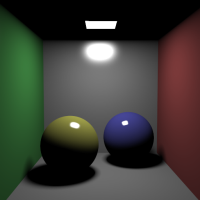
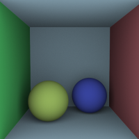
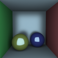
A correct solution to this assignment should produce 8 images for the 8 demo scenes that are almost identical to the following reference images. Please note that since Monte Carlo is based on randomness, and the solution you will reach in this assignment is not optimal, you will almost certainly not create the exact same images because of noise. The goal is to result in images that are unbiased, meaning the mean difference between your images and reference images is plus minus zero. For that, it is useful to save your results in either .hdr or .pfm formats, and compare them in tev, which is a free HDR image viewer with various handy features.
The reference images (download a .zip with .hdr and .pfm images) for direct illumination are:
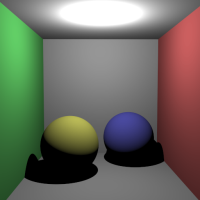 |
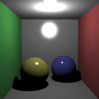 |
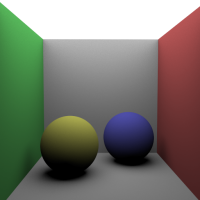 |
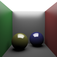 |
| Isotropic point light Diffuse surfaces |
Isotropic point light Glossy surfaces |
Large area light Diffuse surfaces |
Large area light Glossy surfaces |
 |
 |
 |
 |
| Small area light Diffuse surfaces |
Small area light Glossy surfaces |
Const. environment map Diffuse surfaces |
Const. environment map Glossy surfaces |
Assignment 2: Direct illumination estimator based on randomized direction sampling [2+2+4 = 8 points]
The second assignment is very similar to Assignment 1, but you are asked to change the mechanism in which the new ray direction is generated. In Assignment 1, when the ray intersects an object, the new reflected direction is randomly generated by explicitly asking a light source to give you a direction to itself. This is called explicit light source sampling and it ensures that we always make a connection to a light, unless we are in a shadow. This works, but can result in high noise in certain scenes, e.g., at the top of the walls with a large area light.
In Assignment 2, we want you to understand that explicit light source sampling is not the only solution. In fact, one can use any random distribution to sample the reflected directions, as long as you implement it correctly with the corresponding probability distribution function. We want you to try this with three different strategies:
- Assignment 2A (Uniform hemisphere sampling) [2 points]:
The new reflected direction is generated by sampling a uniform hemispherical distribution. - Assignment 2B (Cosine-weighted hemisphere sampling) [2 points]:
The new reflected direction is generated by sampling a cosine-weighted hemispherical distribution. In this case, I do not recommend implementing the solution in PBRT, but instead look at Global Illumination Compendium, pages 19-20, problem (35). The best is to use the first solution, which has a PDF of cosθ/π. It assumes random numbers r1, r2. Notice that cosθ = z, so the PDF you can return is simply z/π. - Assignment 2C (BRDF importance sampling) [4 points]:
The new reflected direction is generated by sampling a distribution proportional to the surface’s BRDF.
To implement this, see the relevant slides 20-28 for a Phong model. You can use the formulas and pseudocode from the slides, but it should also help you to realize that:- The diffuse part of the sampling is the same as the cosine-weighted hemisphere sampling in (2B) above, so you can re-use that code.
- The specular (glossy) part of the sampling is similar, but proportional to the n-th power, which corresponds to the problem (36) on page 20 in the Global Illumination Compendium.
- Keep in mind that the random sampling has 2 branches (diffuse, specular), and its final PDF is not a constant, but instead needs to be combined and re-computed based on which direction you actually ended up choosing!
The rendered images with all of the methods above should eventually converge to the same images as in Assignment 1, but they will have different qualities:
- Assignments 2A, 2B, and 2C do not work for point light sources (scenes 0 and 1). They only generate a black image. Why?
- Compare the results of Assignments 1, 2A, 2B, and 2C. Which solutions result in the best images, with the least amount of noise?
- Cosine-weighted sampling (2B) results in images with slightly less noise than uniform sampling (2A). Why?
- BRDF importance sampling (2C) results in images with significantly less noise than (1), (2A), and (2B). It is the best solution. Why?
I recommend implementing the reflection sampling methods in SampleReflectedDirection in materials.hpp. You will also need to appropriately change the tracing code in pathtracer.hpp, especially, you will need to stop using SamplePointOnLight, and instead use SampleReflectedDirection. Keep in mind that in scenes 6 and 7 with the background environment light, you cannot intersect the background directly, so instead if no intersection is found, use mScene.GetBackground() to retrieve the background light pointer.
All solutions (2A, 2B, 2C) are submitted separately to ReCodEx, because your implementations will have slightly different C++ source codes.
Assignment 3: Multiple importance sampling [8 points]
The third assignment is a combination of Assignments 1 and 2. You are asked to combine the explicit light source sampling (Assignment 1) with the BRDF importance sampling (Assignment 2C) using multiple importance sampling with the balance heuristic.
What does this mean practically?
- When the camera ray hits a surface, you now need to generate two new directions: one using the explicit light source sampling (Assignment 1), and one using the BRDF importance sampling (Assignment 2C).
- Two rays (one in each of the directions) are created and each of them is separately tested whether it hit a light source, and if yes, its contribution is added to the final radiance of the pixel.
- The final PDF of the combined contribution needs to be computed using the balance heuristic formula. In this formula, you need to use the PDF of each of the two strategies, so you will need to implement the PDF methods in materials.hpp and lights.hpp.
Your solution should now work for all scenes 0 to 7, converging to the reference images above with a significantly lower amount of noise.
Assignment 4: Path tracing [4+5+5 = 14 points]
The fourth assignment is about extending the previous assignments into a full path tracer that supports indirect illumination, i.e., paths that bounce more than just once.
The reference images (download a .zip with .hdr and .pfm images) for path tracing are:
 |
 |
 |
 |
| Isotropic point light Diffuse surfaces |
Isotropic point light Glossy surface |
Large area light Diffuse surfaces |
Large area light Glossy surface |
 |
 |
 |
 |
| Small area light Diffuse surfaces |
Small area light Glossy surface |
Const. environment map Diffuse surfaces |
Const. environment map Glossy surface |
We want you to try this with three different strategies, each uploaded separately into ReCodEx:
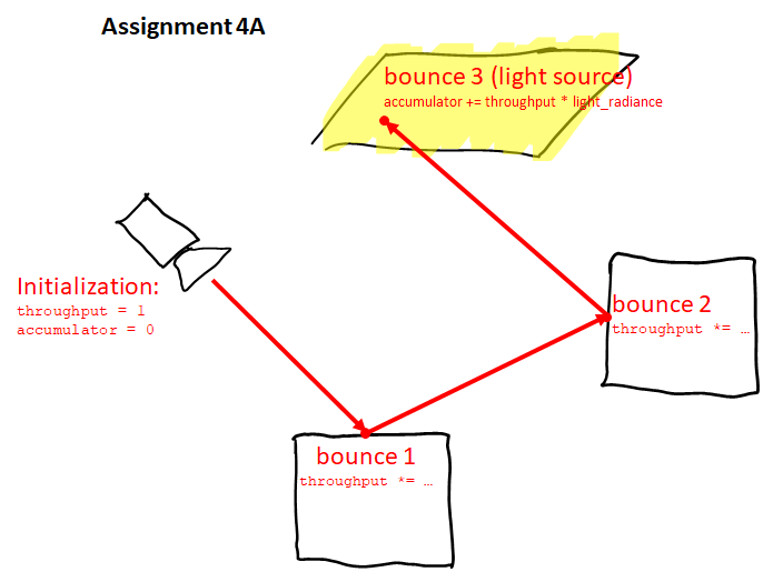
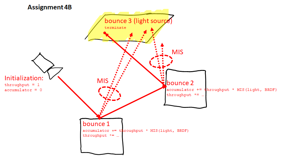
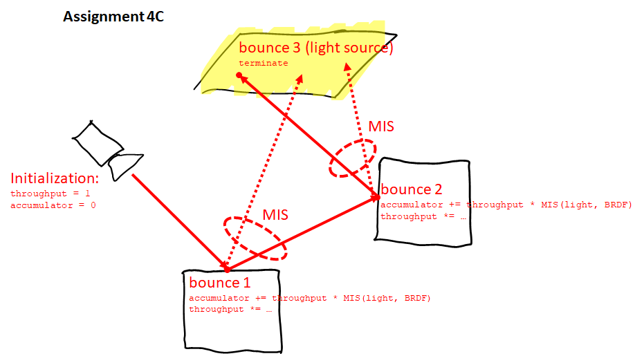
- Assignment 4A (Trivial path tracing) [4 points]:
The most trivial way of implementing path tracing is to simply wrap Assignment 2C into a while(true) loop, such that the code does not terminate until the first bounce, but keeps finding new intersections until a light source is hit. In practice, you need to keep a throughput variable that will be lowered (multiplied) with every bounce, and the final light energy needs to be multiplied by the final throughput of the whole path. To prevent bouncing infinitely, the Russian roulette technique based on the throughput should be implemented. This is all explained in the slides, especially slide 12. Note that this solution will only generate a black image for scenes 0 and 1. - Assignment 4B (Multiple importance sampling, 3 rays per bounce) [5 points]:
A more robust path tracer uses multiple importance sampling, which essentially means merging Assignment 4A with Assignment 3. To keep things simple, implement it the following way. With each bounce, generate 2 new rays with MIS (just like in Assignment 3), and add their contribution to an accumulator variable multiplied by the current path throughput. Then generate a 3rd new ray, which will determine where the path continues towards the next bounce. Note that if you directly hit a light source, you can only add its contribution in the very first bounce, otherwise your estimator would be incorrectly weighted. - Assignment 4C (Multiple importance sampling, 2 rays per bounce) [5 points]:
Similar to Assignment 4B, but in this case, you will not generate a 3rd new ray to continue the path tracing, but instead you will use the 2nd ray (from the BRDF sampling) to continue the tracing. This is more efficient as only 2 rays are required per bounce.
If you have trouble understanding the difference between assignments 4A, 4B, and 4C from the explanation above, perhaps my following images will help:
 |
 |
 |
Assignment 5 (Differentiable rendering in Mitsuba 3) [total: 10 points]
To be explained later.
Archive
Course information for the previous academic years:
